

1$ per unit
basic information
| Nominal Voltage (VDC) | 5 | 6 | 9 | 12 | 18 | 24 | 48 | 0 . 36W |
| Coil Resistance (Ω±10%) | 69 | 100 | 225 | 400 | 900 | 1600 | 6400 | |
| Rated Current (mA) | 71.4 | 60 | 40 | 30 | 20 | 15 | 7. 5 | |
| Max Operate Voltage (VDC) | 3 .75 | 4 . 5 | 6 .75 | 9 | 13 . 5 | 18 | 36 | |
| Min Release Voltage (VDC) | 0 . 25 | 0 . 3 | 0 .45 | 0.6 | 0 . 9 | 1 . 2 | 2 .4 | |
| Coil Resistance (Ω±10%) | 55 | 80 | 180 | 320 | 720 | 1280 | 5120 | 0.45W |
| Rated Current (mA) | 89.3 | 75 | 50 | 37.5 | 25 | 18.7 | 9.375 | |
| Max Operate Voltage (VDC) | 3.8 | 4.5 | 6.8 | 9 | 13.5 | 18 | 36 | |
| Min Release Voltage (VDC) | 0.5 | 0.6 | 0.9 | 1.2 | 1.8 | 2.4 | 4.8 | |
| Max Applicable Voltage | 130% of the rated voltage at 70°C, 170% of the rated voltage at 23°C | |||||||
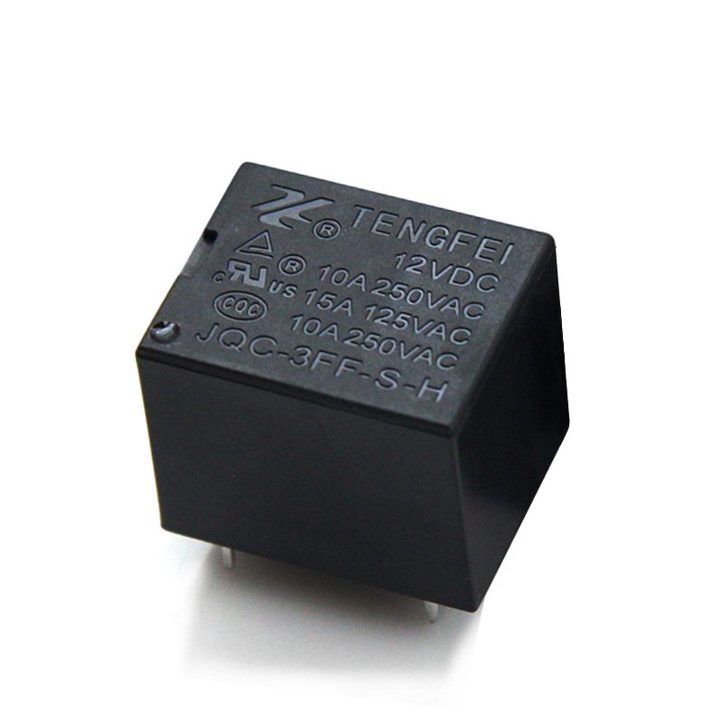
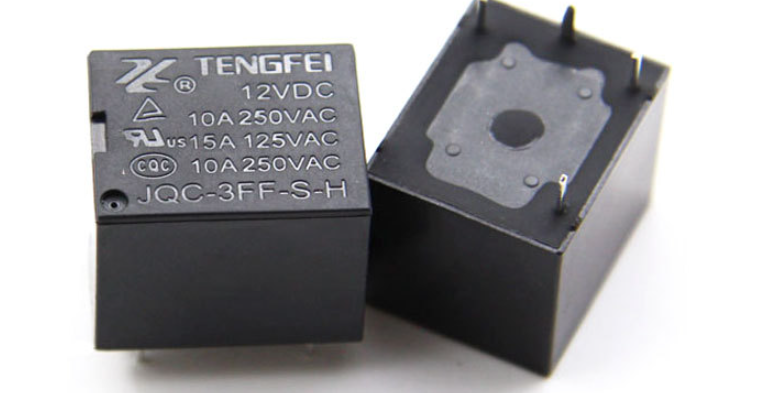
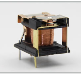
Our relay is an electrically operated switch. It consists of a control circuit and a load circuit. In the control circuit, a relatively small electrical current is used. When this current is applied, it activates an electromagnet within the relay. The electromagnet then causes a mechanical movement which closes or opens the contacts in the load circuit. Relays are widely used in various electrical systems. In automotive electronics, they can be used to control high power devices such as headlights or the starter motor. In industrial control systems, relays are often used for isolation between different parts of a circuit, protecting sensitive components from high voltage or high current surges. They also play an important role in automation processes, allowing for the control of multiple devices based on different electrical signals.

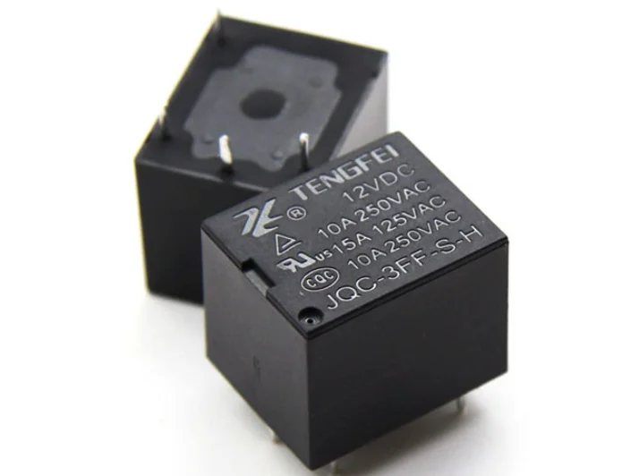
PCB relay JQC-3FF Series product specification
- 10Aswitchingcapability
- Small footprint
- Sealed typeavailable
- ClassB/F available
- Conform toRoHS, ELV directive
- Size19. 2mm*15.4mm*15.4mm(Length * Width * Height)
Declaration: This product specification is for reference only for customers to use. Any changes will not be notified separately.

ORDERING CODE
| JQC – 3FF – S – H 1 2 3 | |
| 1 . Relay Model JQC-T73 2: S: sealed | 3 . Touch point conversion form Z: Form C H: Form A D:FormB |
COIL DATA( at 20℃ )
| Nominal Voltage (VDC) | 5 | 6 | 9 | 12 | 18 | 24 | 48 | 0 . 36W |
| Coil Resistance (Ω±10%) | 69 | 100 | 225 | 400 | 900 | 1600 | 6400 | |
| Rated Current (mA) | 71.4 | 60 | 40 | 30 | 20 | 15 | 7. 5 | |
| Max Operate Voltage (VDC) | 3 .75 | 4 . 5 | 6 .75 | 9 | 13 . 5 | 18 | 36 | |
| Min Release Voltage (VDC) | 0 . 25 | 0 . 3 | 0 .45 | 0.6 | 0 . 9 | 1 . 2 | 2 .4 | |
| Coil Resistance (Ω±10%) | 55 | 80 | 180 | 320 | 720 | 1280 | 5120 | 0.45W |
| Rated Current (mA) | 89.3 | 75 | 50 | 37.5 | 25 | 18.7 | 9.375 | |
| Max Operate Voltage (VDC) | 3.8 | 4.5 | 6.8 | 9 | 13.5 | 18 | 36 | |
| Min Release Voltage (VDC) | 0.5 | 0.6 | 0.9 | 1.2 | 1.8 | 2.4 | 4.8 | |
| Max Applicable Voltage | 130% of the rated voltage at 70°C, 170% of the rated voltage at 23°C | |||||||
CONTACT DATA
| Contact Form | 1H/1Z |
| Contact Material | Silver Alloy |
| Load | Resistive load( COS Ф =1) |
| Contact Ratings | 20A 125VAC 20A 14VDC |
| Minimum load | 100mA 5VDC |
| Max Switching Voltage | 250VAC/30VDC |
| Max Switching Current | 15A |
| Max Switching Power | 2500VA/240W |
| Contact Resistance | 100mΩMax at 6VDC 1A |
| Life Expectancy | Electrical : 100,000 Operations(at30Operations/minute) |
| Mechanical : 10,000,000 Operations(at300Operations/minute) |
CHARACTERISTICS DATA
| Insulation Resistance | 100MΩMin at 500VDC |
| Dielectric Strength Between Open Contacts | 750VAC(50/60Hz for one minute) |
| Between Contacts and coil | 1500VAC(50/60Hz for one minute) |
| Operate Time | 10ms |
| Release Time | 5ms |
| Temperature Range | -40℃ to+85℃ |
| Shock Resistance | Operating Extremes : 10G |
| Damage Limits : 100G | |
| Vibration Resistance | 10-55Hz, 1.5mm |
| Max. switching frequency | Mechanical: 18,000 operations/hr |
| Electrical: 1,800 operations/hr | |
| Humidity | 40-85% |
| Weight | Approx 10g |
| Safety Standard | CQC |

- The dimension tolerance is not noted in the external dimension of the product: when the dimension is 1mm, the tolerance is ± 0.2mm; when the dimension is 1~5mm, the tolerance is ± 0.3mm; when the dimension is> 5mm, the tolerance is ± 0.4mm.
- The tolerance of the unlisted dimension in the installation hole size is ± 0.1mm.
Others
1.All the performance data listed in the data sheet are the initial values tested under standard testing condition.
2.Unsealed relays should be hand soldered to avoid flux contamination of the relay.
3.To avoid using relays under strong magnetic field because it will change the parameters of relay such as pull-in and drop-out voltage.
4.To maintain the performances of relays, please do not make the relay drop or be shocked strongly Suggest that the relays dropped not be used.