


Electric current is like the “blood” of the electric world in daily life. It starts from the power plant, flows along the transmission line, into factories, shopping malls, and homes, and provides power for our electrical equipment. But have you ever thought about how to acckx waoevxx lk mbco knalvy x nburay snesvzk orosaebniphis time, the Current Transformer comes on the scene. It is an indispensable “secret weapon” in the power system!
A current transformer, abbreviated as CT, can be seen from the name that it is closely related to current measurement. Simply put, it is an electrical device that works on the principle of electromagnetic induction. Its function is to convert a large current into a small current in a certain proportion, which is convenient for measurement, protection, and control. From the basic structure, it is mainly composed of an iron core, a primary winding, and a secondary winding, which is a bit like a special transformer. The primary winding has few turns and is directly connected in series in the high current circuit to be measured; the secondary winding has more turns and is connected to the current coil of low-impedance devices such as measuring instruments (such as ammeters, power meters), protection devices (such as relays), etc.
For example, a current transformer is like a current “translator”. The large current “speaks” the “large signal language” that is difficult for us to understand and process directly, and the current transformer “translates” it into a “small signal language” that is easy for us to measure and use. For example, in the power supply system of a large factory, the main line current may be as high as thousands of amperes. It is not only difficult to measure such a large current directly, but it also requires extremely high measurement equipment. Through the current transformer, it can be reduced by a certain proportion and become a standard small current such as 5A or 1A, so that ordinary measuring instruments can also easily “read” it, thereby helping staff understand the operating status of the power system.

Working principle revealed
The law of electromagnetic induction means that when a conductor is in a changing magnetic field, an induced electromotive force will be generated in the conductor; if the conductor forms a closed loop, an induced current will be generated. In the current transformer, the primary winding, secondary winding, and iron core work together to complete the task of current conversion. The primary winding is directly connected in series in the high current circuit to be measured. When the high current passes through the primary winding, it is like injecting energy into the “small universe” of the iron core, generating an alternating magnetic field in the iron core. This magnetic field is like the “spokesperson” of the primary winding current, and its changes are the same as the changes of the primary current.
As the “core component” of the current transformer, the iron core plays a key role in enhancing the magnetic field and concentrating the magnetic flux. It is like a powerful “magnetic field amplifier” that allows the magnetic field to act more effectively on the secondary winding. The secondary winding is tightly wound on the iron core. When the alternating magnetic field in the iron core passes through the secondary winding, according to the law of electromagnetic induction, an electromotive force will be induced in the secondary winding, and then a secondary current will be generated.
Imagine the current transformer as a “music classroom”, and the primary winding is the “big speaker” at the door of the classroom. It plays powerful “current music” (high current), and the sound (magnetic field) generated fills the entire classroom (iron core). The secondary winding is like a “small speaker” in the classroom. After receiving the sound (magnetic field) emitted by the “big speaker”, it also plays music, but the volume (current) is much smaller, which is convenient for us to listen to and analyze (measure and process) easily. Through this “music classroom” conversion, we can more easily understand the situation of the powerful music (large current) originally played by the “big speaker”.
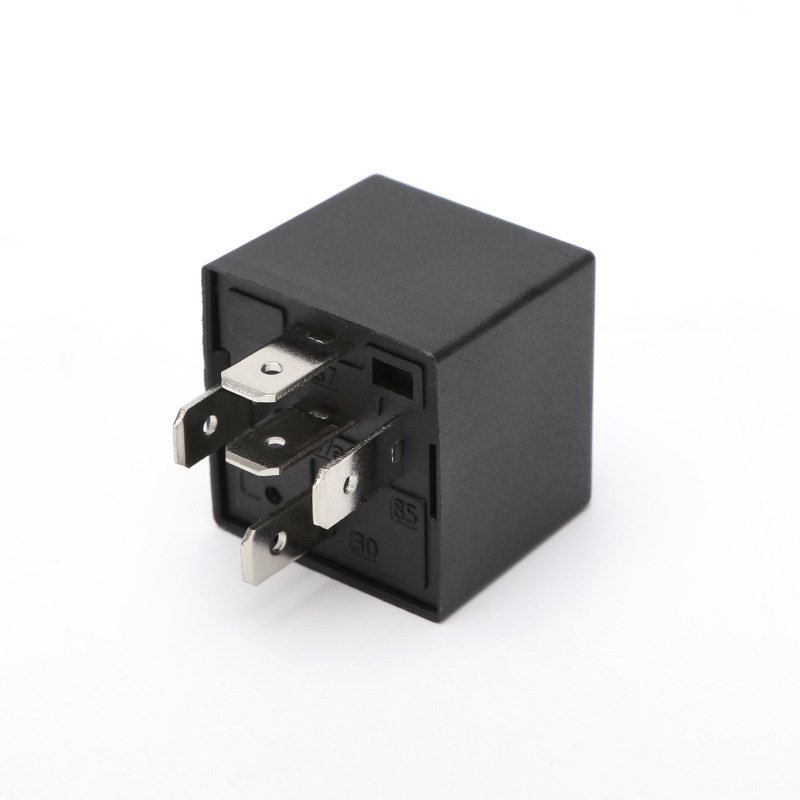
-10-1250/35 Three Phase Dry Type Current Power Distribution Electrical Transformer")
Application scenario broadcast
“Eagle Eye” of the power system
In the huge and complex power system, the current transformer is like a keen “eagle eye”, paying close attention to the current changes in each link, and scorting the stable operation of the power system.
In power plants, the current generated by generators is usually very large, up to thousands or even tens of thousands of amperes. Direct measurement of these large currents is not only difficult but also poses safety risks. The current transformer is very useful here. It can convert the large current output by the generator into a small current in proportion and transmit it to the measuring instrument and protection device. Through these devices, the staff can monitor the current size of the generator in real time and understand its operating status. Once abnormal current fluctuations, such as overload or short circuit, are found, the protection device can quickly act to cut off the circuit to prevent damage to the generator and other equipment.
Substations are key hubs in the power system and play an important role in voltage conversion and power distribution. Here, current transformers are also indispensable. It is used to measure and protect equipment such as transformers and circuit breakers. For example, when monitoring the transformer, the current transformer collects the current data on each side of the transformer in real time. When the transformer has an internal fault, such as a winding short circuit, the current will increase instantly. After the current transformer senses this change, it will quickly transmit the signal to the relay protection device. After the relay protection device determines the fault, it immediately issues a tripping command to make the circuit breaker cut off the fault circuit to prevent the fault from expanding and ensure the safe and stable operation of the substation and the entire power system.
The transmission line is responsible for transmitting electricity from the power plant to various power consumption areas. The distance is long, the voltage is high, and the current is large. Current transformers are installed at key nodes of transmission lines, which can accurately measure the current in the lines, help power dispatchers understand the load of transmission lines, and reasonably allocate power resources. At the same time, when a ground short circuit, phase-to-phase short circuit or other faults occur in the transmission line, the current transformer can capture the fault current in time, provide action basis for the line protection device, quickly cut off the fault line, reduce the scope and time of power outages, and ensure reliable transmission of power.
Industrial Automation “Escort”
In the field of industrial automation, motors, transformers, and other equipment are the core “members” of the production line, and their stable operation is directly related to the continuity of production and product quality. Current transformers are like “escorts” of this equipment, always guarding their safety.
In motor control, current transformers are used to monitor the running current of motors in real time. The current changes during the start, operation, and stop of the motor. By measuring the current through the current transformer, the control system can obtain the running status information of the motor. When the motor is overloaded, the current will exceed the rated value. After the current transformer detects this change, it will feed back the signal to the control system. The control system will immediately take measures, such as reducing the motor speed or cutting off the power supply, to prevent the motor from burning due to overheating and protect the motor and the entire production equipment. At the same time, on some occasions where the motor speed and torque control accuracy is high, such as CNC machine tools and automated production lines, current transformers are also used in current feedback control systems. It feeds back the actual current signal of the motor to the controller. The controller adjusts the power supply voltage and frequency of the motor according to the deviation between the set value and the actual value to achieve precise control of the motor speed and torque, ensuring high precision and stability of the production process.
For transformers current transformers are also crucial. In industrial production, transformers are used to convert high voltages into low voltages suitable for equipment. Current transformers are installed on the primary and secondary sides of the transformer to monitor the current in real time. When the transformer is overloaded, short-circuited, or has a winding fault, the current transformer can detect the abnormal change of the current in time and transmit the signal to the protection device. The protection device quickly acts to cut off the power supply of the transformer to prevent the fault from further deteriorating and ensure the safety of production. For example, in a steel plant, large transformers power numerous production equipment. Once a transformer fails, the entire production line may be paralyzed, causing huge economic losses. The existence of current transformers is like installing a “protective cover” for the transformer, which can detect and handle faults in time to ensure the smooth progress of production.

“Regulator” in the field of new energy
With the growing global demand for clean energy, new energy systems such as photovoltaic power generation and wind power generation have been widely used. However, new energy power generation is intermittent and volatile, which poses challenges to the stable operation of the power system. In this field, current transformers are like “regulators” to help new energy systems cope with these challenges and achieve efficient and stable power generation.
In photovoltaic power generation systems, solar panels convert solar energy into direct current, which is then converted into alternating current through inverters and connected to the grid. Due to changes in light intensity, temperature, and other factors, the output current of the photovoltaic power generation system will fluctuate. Current transformers are installed at the input and output ends of the inverter to monitor the magnitude and changes of the current in real time. By analyzing the current data, the control system can accurately control the inverter according to the needs of the power grid and the actual output of the photovoltaic power generation system, adjust the size and phase of the output current to match the requirements of the power grid, achieve maximum power tracking, and improve the efficiency of photovoltaic power generation. At the same time, when the photovoltaic power generation system fails, such as panel failure, inverter failure, etc., the current transformer can quickly detect the current anomaly, trigger the protection mechanism in time, prevent the fault from expanding, and ensure the safe operation of the photovoltaic power generation system. For example, in a large photovoltaic power station, many solar panels form an array to generate electricity. The current transformer monitors the current of each panel group and inverter in real time. Once a panel group fails and causes a current anomaly, the system can immediately detect and take measures, such as cutting off the circuit of the faulty part to ensure that other normal panel groups continue to generate electricity and reduce power generation losses.
Wind power generation systems are also inseparable from current transformers. The output current of wind turbines fluctuates with changes in wind speed, and the current characteristics are different under different operating conditions, such as startup, grid connection, normal operation, and shutdown. The current transformer is installed in the electrical system of the wind turbine to measure the current signal accurately and transmit it to the control system. The control system adjusts the blade angle and speed of the wind turbine according to the current information, combined with data such as wind speed and wind direction, to achieve optimized control of wind power generation so that the wind turbine can operate stably under different wind speed conditions and output high-quality electricity. In addition, the current transformer also plays a key role in the protection of wind power generation systems. When the system fails, such as short circuit and overload, the current transformer detects the abnormal current and quickly activates the protection device to protect the safety of the wind turbine and the entire power generation system. For example, in offshore wind farms, the environment is harsh, and the wind changes are complex. The current transformer can work stably under such conditions, providing a strong guarantee for the reliable operation of the wind power generation system.
“Safety Guard” in the field of transportation
In the field of transportation, especially in the rail transit system, the current transformer provides an important guarantee for the safe operation of the train, which can be called a “safety guard”.
The train contact network of the rail transit system provides power for the train, and its voltage is usually high, and the current is also large. The current transformer is installed in the power supply line of the contact network and is mainly used to monitor and control the current of the contact network. It converts high voltage and large current into low voltage and small current, which is convenient for monitoring and controlling the access and operation of equipment. By monitoring the contact network current in real time, the staff can understand the power consumption of the train and determine whether there is a fault in the contact network. When the contact network has a short circuit, a broken line, or other faults during the operation of the train, the current transformer can quickly detect the abnormal change of the current and transmit the signal to the protection device and the control system.
The protection device immediately acts to cut off the power supply to prevent the accident from expanding and ensure the safety of the train and passengers. At the same time, the control system can also analyze and adjust the running status of the train according to the data provided by the current transformer to achieve energy-saving operation and optimized scheduling of the train. For example, in the urban subway system, each subway train obtains electricity through the contact network. The current transformer monitors the contact network current in real time. Once an abnormality is found, timely measures can be taken to ensure the safe operation of the subway and avoid the suspension of the train due to power supply failure, which affects the urban traffic order. In addition, in some modern rail transit systems, current transformers are also used to achieve remote monitoring and intelligent operation and maintenance. By combining current transformers with communication technology, the collected current data is transmitted to the control center in real time. The staff of the control center can remotely grasp the operating status of the contact network and trains in real time, discover potential fault hazards in advance, and arrange for maintenance personnel to deal with them in time, to improve the reliability and operation efficiency of the rail transit system.
The “Guardian” of the Communication System
In the communication system, although the current transformer is not as eye-catching as in the power system, it plays an important role silently and can be called the “Guardian” of the communication system.
The communication system has extremely high requirements for stability and reliability. Any interference may cause communication interruption or signal distortion. Current transformers are mainly used here for lightning protection and anti-interference. Communication lines, especially outdoor overhead lines or underground cables, are easily affected by natural factors such as lightning. When lightning strikes the communication line, it will instantly generate a strong current and voltage shock, which may damage the communication equipment. The current transformer can reduce the high current to a measurable or controllable low current and cooperate with lightning protection devices, such as lightning arresters, to introduce the overcurrent generated by lightning into the earth to protect the communication equipment from damage by lightning. At the same time, there are various electromagnetic interference sources in the communication system, such as nearby power equipment, wireless signals etc., which will affect the quality of the communication signal.
The current transformer isolates and suppresses the interference current through its electromagnetic characteristics, reduces the impact of interference on the communication signal, and ensures the stable operation of the communication system. For example, in a mobile communication base station, the current transformer is installed in the power supply line and the signal transmission line. On the one hand, it prevents lightning from damaging the base station equipment, and on the other hand, it effectively resists the surrounding electromagnetic interference to ensure smooth communication between the base station and the mobile terminal.
In addition, in some communication systems that require high-precision signal transmission, such as satellite communication, optical fiber communication, etc., current transformers are also used for signal isolation and conversion to ensure the accuracy and stability of the signal during transmission, providing strong support for the development of modern communication technology.

A complete analysis of the advantages and disadvantages
Significant advantages
- High-precision measurement: Within the rated current range, the current transformer can provide extremely high measurement accuracy with minimal error. This makes it play a key role in the metering and monitoring of the power system and can provide accurate data support for power operation and management. For example, in electric energy metering, high-precision current transformers can ensure the accuracy of power calculation and ensure fair billing between power companies and users. Common high-precision current transformers have an accuracy level of up to 0.1 or even higher, which means that under rated conditions, its measurement error can be controlled within a very small range, such as within 0.1%, providing a solid guarantee for the accurate measurement and analysis of the power system.
- High isolation voltage: The current transformer has a high isolation voltage between the primary and secondary windings. This feature effectively isolates the high-voltage primary circuit from the low-voltage secondary measurement and protection equipment. In the power system, the primary side is usually connected to high-voltage and high-current lines, while the secondary side is connected to measuring instruments and protection devices that are easily accessible to operators. High isolation voltage can prevent high voltage on the primary side from entering the secondary side, thus ensuring the safety of equipment and personnel. For example, in a substation, even if the voltage on the primary side is as high as tens of kilovolts or even higher, the staff on the secondary side can safely perform measurements and maintenance operations due to the high isolation performance of the current transformer. Generally speaking, the isolation voltage of medium and high voltage current transformers can reach thousands of volts or even higher, which can effectively resist various electrical interferences and overvoltage shocks and ensure the safe and stable operation of the power system.
- Low cost: In power frequency applications, current transformers have the advantage of relatively low cost. Compared with some other types of current measurement devices, such as Hall effect sensors, the manufacturing process of current transformers is relatively mature, and the material cost is relatively controllable. This enables it to effectively reduce the construction and operation costs of the system when it is used on a large scale in the power system. For example, in the distribution system of the urban power grid, current transformers are widely used for current measurement and protection. Due to their cost advantages, economical and efficient power monitoring and control can be achieved while ensuring system performance. Especially for some cost-sensitive application scenarios, such as the internal power supply system of industrial enterprises, the low-cost characteristics of current transformers make them the preferred current measurement equipment.
Disadvantages
- AC measurement limitations: Current transformers are only suitable for measuring AC currents, which is determined by their working mode based on the principle of electromagnetic induction. For DDC, since its magnitude and direction do not change with time, it is impossible to generate an alternating magnetic field in the core of the current transformer, and electromagnetic induction cannot be achieved, so it cannot be measured by a current transformer. This limitation is particularly prominent in some occasions where AC and DC currents need to be measured simultaneously. For example, in the battery management system of new energy vehicles, it is necessary to monitor both the DC charging and discharging current of the battery and the AAC when the motor is running. At this time, the current transformer cannot meet all the measurement requirements and needs to be matched with other sensors suitable for DC measurement, such as Hall sensors.
- Overload error problem: When the current transformer is overloaded or saturated, its error will increase sharply. This is because under overload or saturation conditions, the magnetic flux density in the core will exceed the normal range, causing the magnetic permeability to decrease, thereby changing the proportional relationship between the primary current and the secondary current and no longer meeting the normal conversion ratio. For example, when a short circuit occurs in the power system, the current will increase sharply and instantly, which may cause the current transformer to saturate. At this time, the current signal output by the secondary side cannot accurately reflect the actual current size of the primary side, which may cause misjudgment or misoperation of measuring instruments and protection devices that rely on current signals for judgment and action, affecting the safe operation of the power system. To avoid this situation, when selecting a current transformer, it is necessary to reasonably select its rated current according to the actual application scenario to ensure that the current transformer can maintain good performance in normal operation and possible overload conditions.
- Limited volume installation: For current transformers with large current models, their volume is often large. This is because, to meet the measurement requirements of large currents, it is necessary to increase the cross-sectional area of the primary winding and the size of the core to reduce the winding resistance and increase the magnetic permeability. Larger volumes will be limited in some occasions where installation space is limited. For example, in some compact switch cabinets and distribution boxes, it may not be possible to install larger current transformers. In addition, large current transformers will also cause inconvenience during transportation, installation, and maintenance, increasing the difficulty and cost of project implementation. In some application scenarios with strict requirements on equipment volume, such as small power generation equipment and energy storage devices in distributed energy systems, large current transformers may not meet the installation requirements, and it is necessary to find smaller and more compact current measurement solutions.

Selection and Usage Guide
Selection Points
- Rated current matching: It is very important to select a current transformer with a suitable rated current according to the size and range of the measured current. If the measured current exceeds the rated current of the current transformer, it may cause the transformer to saturate, causing the measurement error to increase sharply or even damage the equipment. For example, in an industrial plant, the maximum working current of a production line is 800A. When selecting a current transformer, its rated primary current should be greater than 800A. A 1000/5A current transformer can be selected. This can ensure the accuracy of measurement during normal operation and ensure that the transformer can still operate reliably when the current fluctuates to a certain extent. Generally speaking, to ensure the accuracy of measurement and the service life of the transformer, it is recommended that the measured current be within the range of 60% to 20% of the rated primary current of the current transformer.
- Accuracy level selection: Different measurement accuracy requirements require different accuracy levels of current transformers. Common accuracy levels are 0.1, 0.2, 0.5, 1, 3, etc. The smaller the number, the higher the accuracy. For example, in the field of electric energy metering, to ensure the accuracy of electric quantity calculation, a current transformer of level 0.2 or level 0.5 is usually selected; while in some industrial process monitoring with relatively low measurement accuracy requirements, a current transformer of level 1 or level 3 may be sufficient to meet the needs. When selecting the accuracy level, the cost factor also needs to be considered because the higher the accuracy level, the higher the price of the current transformer. Therefore, on the premise of meeting the measurement accuracy requirements, the appropriate accuracy level should be selected by comprehensively considering factors such as cost.
- Insulation form adaptation: The installation environment has an important influence on the choice of insulation form of the current transformer. In dry and dusty indoor environments, dry-type current transformers are a more common choice due to their simple structure and easy maintenance; in humid, dusty,o r corrosive gas environments, oil-immersed current transformers or epoxy resin cast insulation current transformers are more advantageous. They can provide better insulation performance and protection capabilities to ensure the stable operation of current transformers in harsh environments. For example, in a substation near the sea, due to the high humidity and the presence of corrosive substances such as salt, epoxy resin-insulated current transformers with good moisture and corrosion resistance are usually selected to ensure the safe and reliable operation of the equipment. At the same time, factors such as installation space and fire protection requirements need to be considered to ensure that the selected insulation form of the current transformer is fully compatible with the actual installation environment.
Precautions for use
- Correct connection to avoid short circuit and open circuit: When installing the current transformer, it is necessary to ensure that the primary and secondary sides are connected correctly. The primary side should be connected in series in the circuit to be measured, and the secondary side should be connected in series with loads such as measuring instruments and protective devices. It should be noted that the secondary side is not allowed to be open-circuited, because once the secondary side is open-circuited, the primary side current will be completely converted into excitation current, resulting in severe saturation of the iron core, a sharp increase in magnetic flux, and extremely high voltage will be induced in the secondary winding, which will not only damage the current transformer itself, but also endanger the personal safety of the operator. At the same time, short circuits on the secondary side should also be prevented. Short circuits will cause excessive current on the secondary side, which may damage measuring instruments or protective devices. For example, during an electric power maintenance process, the staff mistakenly opened the secondary side of the current transformer, and the high voltage generated instantly caused the nearby equipment housing to be charged. Fortunately, it was discovered and handled in time to avoid serious accidents. Therefore, during installation and use, it is necessary to strictly follow the operating procedures to connect, ensure that the connection is firm and reliable, and regularly check whether the connection parts are loose or oxidized.
- Regular maintenance and calibration to ensure accuracy: Regular maintenance and calibration of current transformers are the key to ensuring their measurement accuracy and reliability. Maintenance work includes cleaning the surface of the current transformer to prevent dust, dirt, etc. from accumulating and affecting heat dissipation and insulation performance; checking whether the terminal is loose and hot to ensure good connection; checking whether the appearance of the transformer is damaged, cracked, etc. Abnormal conditions. Calibration uses standard current sources and measuring instruments to detect the parameters such as the ratio and error of the current transformer, to ensure that its performance meets the requirements. Generally speaking, for important power systems and high-precision measurement occasions, it is recommended to perform calibration at least once a year; for general industrial applications, calibration can be performed every 2-3 years according to actual conditions. Through regular maintenance and calibration, problems with current transformers can be discovered in time, and corresponding repair or replacement measures can be taken to ensure the safe and stable operation of the power system.
- Load matching to avoid performance impact: The matching of the secondary side load has an important impact on the performance of the current transformer. The secondary side load of the current transformer should be within its rated capacity. If the load is too large, the secondary side current will decrease, a nd the error will increase; if the load is too small, although it will not directly affect the measurement accuracy, it may cause a waste of resources. For example, the rated capacity of a current transformer is 15VA, and the load corresponding to the total impedance of the measuring instrument and wire connected to the secondary side is 20VA, which exceeds the rated capacity and will cause a large deviation in the measurement result. Therefore, when selecting the secondary side load, it is necessary to reasonably calculate and configure the load according to the rated capacity of the current transformer and the input impedance of the measuring instrument to ensure load matching. At the same time, attention should also be paid to the length and cross-sectional area of the secondary side connecting wire. The wire length should be shortened as much as possible, and the wire cross-sectional area should be increased to reduce the impact of the wire resistance on the load.
Outlook for future development trends
Fiber-optic current transformers are emerging: fiber-optic current transformers are based on the Faraday magneto-optical effect and use optical fibers as sensing elements. They have many advantages, such as small size, light weight, good insulation performance, and fast response speed, and have become a hot topic for current research and development. For example, the invention patent “A system and method for monitoring the scale factor of fiber-optic current transformers” obtained by Changfei Fiber Optics can effectively determine the scale factor of current transformers through the design of unique systems and methods, realize online monitoring, greatly reduce the impact of light source optical power attenuation on measurement stability, and improve the measurement accuracy and operation reliability of fiber-optic current transformers. In terms of technical principles, when linearly polarized light propagates in optical fibers, if it is affected by an external magnetic field, its polarization plane will rotate, and the rotation angle is proportional to the magnetic field strength and the distance the light propagates in the magnetic field. By measuring the angle of rotation of the polarization plane, the magnitude of the current can be calculated indirectly. Compared with traditional current transformers, fiber-optic current transformers are not subject to electromagnetic interference and can achieve high-precision measurement. In the future, they are expected to be more widely used in high-voltage and large-capacity power systems.
Breakthrough innovation of optical current transformer: The Optical current transformer is also one of the important directions of future technological innovation. It uses optical technology to measure current with higher accuracy and wider application scenarios. The patent of “A method and system for detecting measurement error degradation of optical current transformer” obtained by China Electric Power Research Institute combines advanced optical technology and data processing algorithms. Through the data collection and analysis of optical current transformer in actual operation, it can monitor its performance changes in real time, quickly identify equipment failures, and avoid a series of economic losses and safety hazards caused by measurement errors, which is crucial to the safe operation of power systems. With the continuous advancement of technology, optical current transformers will develop in the direction of higher accuracy, more stability and reliability, and intelligence, providing stronger support for the precise monitoring and intelligent operation and maintenance of power systems. For example, in the future smart grid, optical current transformers can be combined with AI data analysis technology to achieve higher-level data processing and fault prediction, truly achieve intelligent maintenance, and greatly improve the overall management efficiency and response speed of the power system.