Parameter
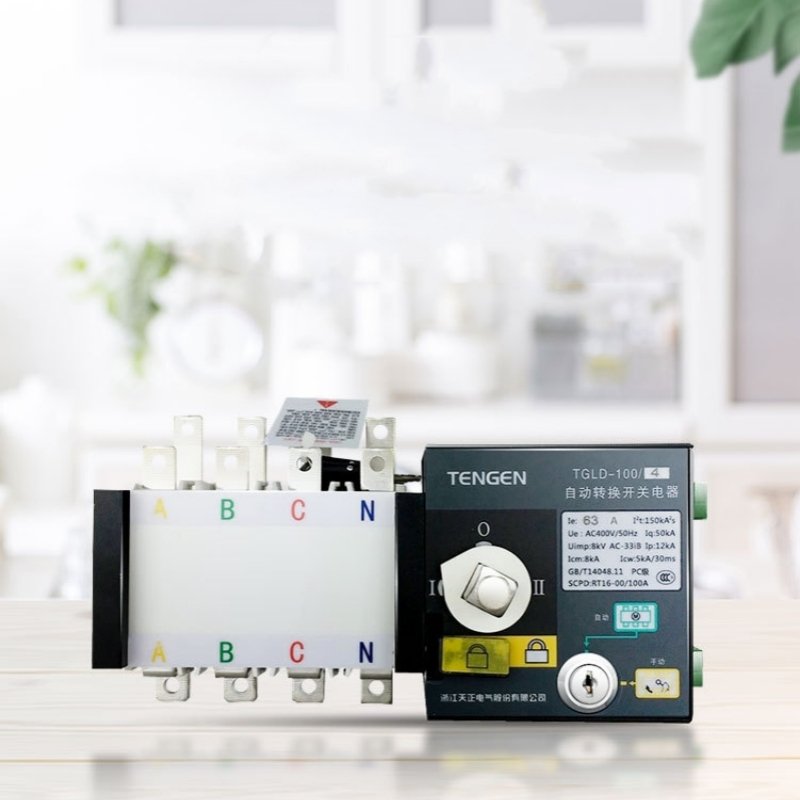
| Product model | TGLD-100 | TGLD-160 | TGLD-250 | TGLD-400 | TGLD-630 | TGLD-1000 | TGLD-1250 | TGLD-1600 |
| Standard | GB/T14048.11 |
| Current specifications(A) | 16,20,25,32,40,50,63,80, 100 | 100,125,140,160 | 160,180,200,225, 250 | 250,315,350,400 | 400,500,630 | 630,700, 800,1000 | 1250 | 1600 |
| Rated operational voltage(Ue) | AC400V 50Hz |
| Rated insulation voltage (Ui) | 690V | 1000V |
| Rated impulse withstand voltage(Uimp) | 8kV | 12kV |
| Rated short-time withstand current Icw(kA) | 5/30ms | 10/30ms | 12.6/60ms | 32/60ms |
| Rated short-time making capacity Icw(kA) | 8 | 17 | 25.2 | 67.2 |
| Rated short-circuit limiting current | Front fuse | Front fuse |
| 50 | 9 |
| No. of poles | 3P,4P |
| Utilization category | AC-33iB |
| Electrical grade | PC level |
| Electromagnetic compatibility environment | B environment |
| Pollution degree | 3 |
| Installation method | Vertical fixed installation |
| Connection | Screw wiring |
| operating mode | Automatic, manual, cabinet door electric button control |
| Tightening torque of screws(N m) | 12 | 20 | 20 | 25 |
| Screw breaking torque (N m) | 15 | 50 |
| Mechanical life | 9000(*) | 6000(*) | 4000(*) |
| Electrical life | 3000(*) | 2000(*) | 2000(*) |
| The maximum number of conductors allowed to be clamped in | 1 pieces | 2 pieces |
| switch position | Common position (Ⅰ), backup position(Ⅱ), disconnect position(0) |
| pollution degree | 3 level |
| protection grade | IPOO |
| Contact transfer time(s) | 0.95±30% | 0.40±30% | 0.26±30% | 0.30±30% | 0.30±30% | 0.65±30% |
| operating transfer time(s) | 4.4±10% | 4.88±10% | 4.67±10% | 4.80±10% | 4.80±10% | 6.15±10% |
| Return time(s) | 4.68±10% | 4.68±10% | 4.64±10% | 4.50±10% | 4.50±10% | 5.70±10% |
| off time(s) | 0.93±20% | 0.36±20% | 0.25±20% | 0.30±20% | 0.30±20% | 0.60±20% |
| Range of power supply voltage deviation | Undervoltage conversion 160V ± 10% |
| Voltage hysteresis V | Fixed undervoltage value (default 160V)+20V ± 10% |
| control characteristics | Loss of voltage, undervoltage, phase transition |
| Rated control power supply voltage | AC230V 50Hz |
| Installation method of control electrical appliances | Integrated |
| Normal working range | 85% Ue~110%Ue |
| Return conditions | Self investment and self recovery (customizable for self investment or non self recovery) |
| Controller power consumption | ≤5 | ≤10 |
Normal working conditions and installation conditions
- Surrounding air temperature: The upper limit of the surrounding air temperature is +40 ℃, the lower limit is -5 ℃, and the average temperature within 24 hours does not exceed +35 ℃.
- Altitude: The altitude of the installation site shall not exceed 2000m
- Atmospheric conditions: The relative humidity of the atmosphere does not exceed 50% at the highest ambient temperature of +40℃, and can have higher relative humidity at lower temperatures, such as reaching 90% at +20 ℃. Special measures should be taken for occasional condensation caused by temperature changes
Features and functions
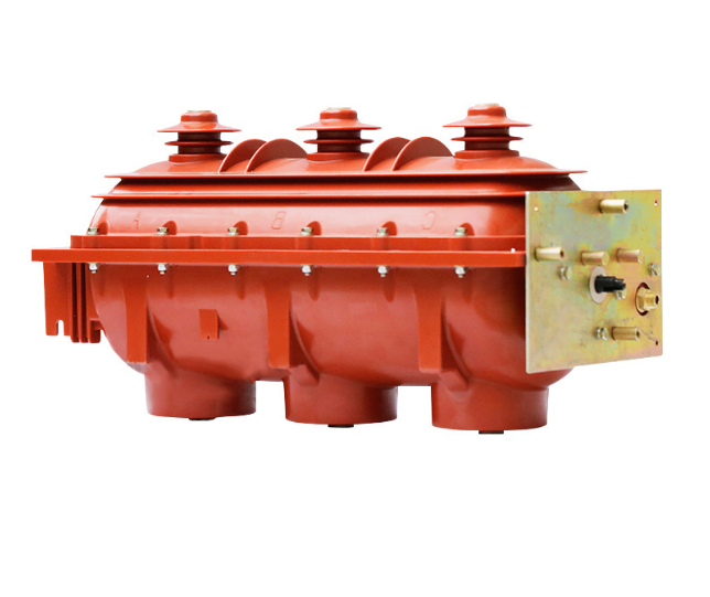
Adopting double row composite contacts, embedded mechanism, micro motor pre energy storage and microelectronic control technology, short arcing distance. Reliable mechanical and electrical interlocks are adopted, and independent load isolation switches are used for the execution components, ensuring safe and reliable use.Adopting zero crossing technology, it can be forcibly reset to zero in emergency situations (while cutting off two power sources) to meet the needs of fire linkage. The load isolation switch is driven by a single motor for reliable and smooth switching, with no noise and low impact force.
The operator drives the motor to only pass current at the moment of switching the load isolation switch, ensuring stable operation without the need for working current, resulting in significant energy savings.
The load isolation switch is equipped with a mechanical interlocking device to ensure reliable and non interfering operation of the commonly used and backup power sources.
It has obvious on/off position indication, padlock and other functions, reliably achieving isolation between power supply and load.
Good safety performance, high degree of automation, and high reliability.
The product has a zero position state.
Easy to install, the control circuit adopts plug-in terminal connection.
Operation function: manual operation, automatic control operation. Manual operation is prohibited in automatic mode. If manual operation is required, the automatic electrical lock must be turned off to the manual position


 Controller function
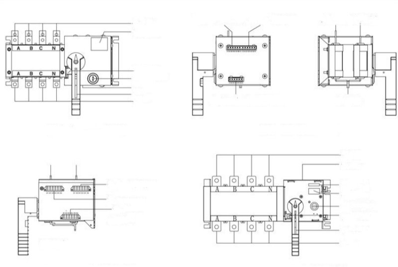 Electrical key lock:control the power supply of the internal control circuit of the control switch. The electrical lock is in the automatic position, and the switch can be operated automatic position,and the switch can only be only