Product Pictures


Structure


Product Pictures
Structure
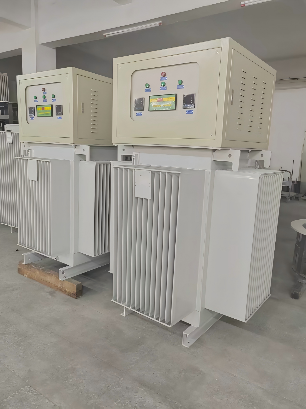
A distribution transformer, typically located near consumer load points, is a step-down transformer used in power systems. It decreases the high voltage to a safer, user-friendly level. Common voltage ratings range from 11 kV to 110 V. These transformers are designed for peak efficiency at 60-70% load utilization.
Looking for the most cost-effective solution for your power needs? Check out our competitively priced three-phase and single phase meter box price.
A power transformer is mainly used to transmit high electric power at high voltage levels through power lines to the distribution centers. They generally have high MVA ratings. Power transformers are mainly used for increasing low voltage levels to high voltage levels for transmission, maximizing efficiency at or close to full loads.
Technical Specification
| Single Phase Pole Mounted Transformer | ||||
| Rated Power (KVA) | High Voltage (KV) | Low Voltage (V) | Loss (W) | |
| No-load Loss (W) | On-load Loss (W) | |||
| 10 | 24.94/14.4kV 12.47/7.2kV 34.5KV/ 19.92KV/ 13.8KV/ 13.2KV/ or others | 120/240V 480Y/ 277V 600Y/ 347V | 36 | 120 |
| 15 | 50 | 195 | ||
| 25 | 80 | 290 | ||
| 37.5 | 105 | 360 | ||
| 50 | 135 | 500 | ||
| 75 | 190 | 650 | ||
| 100 | 210 | 850 | ||
| 167 | 350 | 1410 | ||
| 333 | – | – | ||
| Technical Data For Single Phase Pole Mounted Transformer CSP Type | |||||
| Rate power | High voltage | Low voltage | No load losses(w) | On load losses(w) | Weight(kg) |
| 10kVA | 34500/19920V 13800/7957V 13200/7620V 12470/7200V or others | 120-240V 240-480V 347V 600V | 50 | 120 | 150 |
| 15kVA | 65 | 195 | 205 | ||
| 25kVA | 105 | 290 | 245 | ||
| 37.5kVA | 140 | 360 | 335 | ||
| 50kVA | 180 | 500 | 370 | ||
| 75kVA | 250 | 650 | 505 | ||
Product Paramenters
| Single Phase Pole Mounted Transformer | |||||||
| Rated Power (KVA) | High Voltage (KV) | Low Voltage (V) | Dimension(mm) | Weight(KG) | |||
| W | D | H | Oil Weight | Total Weight | |||
| 5KVA | 24.94/14.4kV 12.47/7.2kV 34.5KV/ 19.92KV/ 13.8KV/ 13.2KV/ or others | 120/240V 480Y/ 277V 600Y/ 347V | 465 | 485 | 855 | 15 | 92 |
| 10KVA | 500 | 525 | 885 | 22 | 150 | ||
| 15KVA | 520 | 565 | 905 | 30 | 210 | ||
| 25KVA | 560 | 590 | 935 | 45 | 258 | ||
| 37.5KVA | 610 | 625 | 935 | 50 | 340 | ||
| 50KVA | 635 | 675 | 1035 | 62 | 395 | ||
| 75KVA | 745 | 840 | 1035 | 88 | 480 | ||
| 100KVA | 770 | 965 | 1035 | 94 | 530 | ||
| 167KVA | 795 | 890 | 1035 | 138 | 680 | ||
| 250KVA | 988 | 1001 | 1035 | 150 | 780 | ||
| 333KVA | 1012 | 1015 | 1035 | 172 | 850 | ||
D11-M1.R series single-phase column distribution transformer parameters(ordinary silicon steel sheet iron core)
| Model | Cap.(kVA) | Voltage (V) | Loss (W) | Dimensions(mm) | Weight (kg) | |||||||
| HV | Tap range | LV | No load | Load | A | B | C | D | Oil | Gross | ||
| D11-3 | 3 | 33000 30000 17321 11547 13800 7967 7620 6350or other | ±2×2.5% Or other | 120 220 240 250 or other | 9 | 45 | 800 | 400 | 500 | 300 | 10 | 70 |
| D11-5 | 5 | 19 | 75 | 860 | 430 | 510 | 340 | 15 | 92 | |||
| D11-10 | 10 | 36 | 120 | 910 | 470 | 550 | 380 | 22 | 150 | |||
| D11-15 | 15 | 50 | 195 | 970 | 500 | 580 | 410 | 30 | 210 | |||
| D11-25 | 25 | 80 | 290 | 1025 | 550 | 630 | 450 | 45 | 258 | |||
| D11-37.5 | 37.5 | 105 | 360 | 1225 | 630 | 680 | 520 | 50 | 340 | |||
| D11-50 | 50 | 135 | 500 | 1235 | 630 | 680 | 520 | 62 | 395 | |||
| D11-75 | 75 | 190 | 650 | 1300 | 680 | 720 | 550 | 88 | 480 | |||
| D11-100 | 100 | 210 | 850 | 1350 | 780 | 810 | 610 | 94 | 530 | |||
| D11-167 | 167 | 350 | 1410 | 1460 | 830 | 890 | 660 | 138 | 680 | |||
| D11-250 | 250 | 500 | 2000 | 1570 | 960 | 950 | 660 | 250 | 990 | |||
| D11-333 | 333 | 650 | 2500 | 1660 | 960 | 960 | 660 | 300 | 1160 | |||
The above data is for reference only and can also be customized according to user requirements.
Workshop

Certificate

FAQ