


4~35$ depends on specific type
basic information
| Installation category | Working and installation conditions |
| Type | Ⅲ |
| class of pollution | 3 |
| Compliant with standards | GB/T 14048.1/IEC 60947-1、GB/T 14048.4/IEC 60947-4-1、 GB/T 14048.5/IEC 60947-5-1、GB 21518 |
| authentication | CE、CCC |
| Shell protection level | NXCF-06M~38 is IP20( Only applicable to the front side);NXCF-40~100 is IP10 ;NXCF-120~630 is IP00 |
| Surrounding air temperature | The maximum working temperature is -35 ℃~+70 ℃, the normal working temperature is -5 ℃~+40 ℃, and the average value within 24 hours does not exceed+35 ℃. If not used within the normal operating temperature range, please refer to the appendix “Instructions for Non normal Environment Use” for details |
| above sea level | Not exceeding 2000m, if not used within this range, refer to the Appendix “Instructions for Abnormal Environment Use” |
| Atmospheric conditions | When the maximum temperature is+70 ℃, the relative humidity of the air does not exceed 50%. Higher relative humidity can be allowed at lower temperatures, such as reaching 90% at+20 ℃. Special measures should be taken for occasional condensation caused by humidity changes. |
| Installation conditions | The inclination angle between the installation surface and the vertical surface shall not exceed ± 5 ° |
| Shock and vibration | The product should be installed and used in a place without significant shaking, impact, and vibration |
1 Scope of application
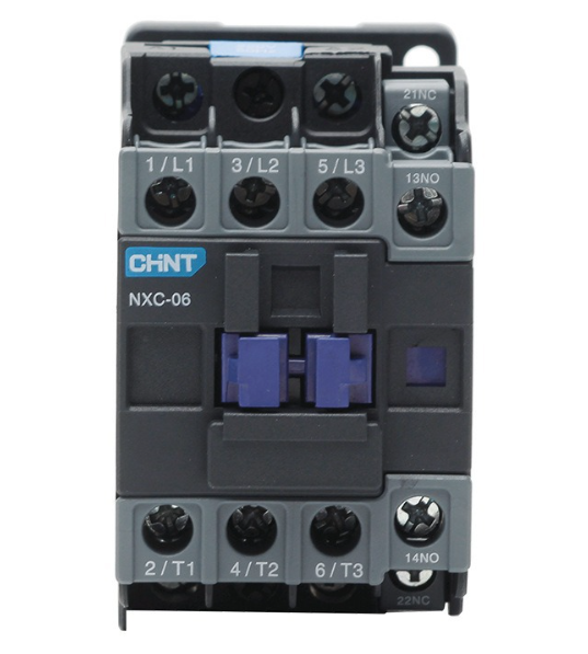
The all-new NXCF series AC contactor has a novel appearance and compact structure. Mainly used for frequent starting and control of AC motors, remote connection and disconnection of circuits, and can be combined with appropriate thermal overload relays to form electromagnetic starters.
Compliant with standards:GB/T 14048.1/IEC 60947-1、GB/T 14048.4/IEC 60947-4-1、 GB/T 14048.5/IEC60947 -5-1、GB 21518.

2 main parameter
2.1 Rated working current Ie:6A~630A
2.2 Rated working voltage Ue:220V~690V
2.3 Rated insulation voltage:690V(NXCF-06(M)~100)、1000V(NXCF-120~630)
2.4 number of poles:3P、4P( 仅 NXCF-06M~12M)
2.5 Coil control method:AC(NXCF-06(M)~225)、DC(NXCF-06M~12M)、AC/DC(NXCF-265~630)
2.6 Installation method:NXCF-06M~100 Installation of card rails and screws、NXCF-120~630 Screw installation

3 Working and installation conditions
| Installation category | Working and installation conditions |
| Type | Ⅲ |
| class of pollution | 3 |
| Compliant with standards | GB/T 14048.1/IEC 60947-1、GB/T 14048.4/IEC 60947-4-1、 GB/T 14048.5/IEC 60947-5-1、GB 21518 |
| authentication | CE、CCC |
| Shell protection level | NXCF-06M~38 is IP20( Only applicable to the front side);NXCF-40~100 is IP10 ;NXCF-120~630 is IP00 |
| Surrounding air temperature | The maximum working temperature is -35 ℃~+70 ℃, the normal working temperature is -5 ℃~+40 ℃, and the average value within 24 hours does not exceed+35 ℃. If not used within the normal operating temperature range, please refer to the appendix “Instructions for Non normal Environment Use” for details |
| above sea level | Not exceeding 2000m, if not used within this range, refer to the Appendix “Instructions for Abnormal Environment Use” |
| Atmospheric conditions | When the maximum temperature is+70 ℃, the relative humidity of the air does not exceed 50%. Higher relative humidity can be allowed at lower temperatures, such as reaching 90% at+20 ℃. Special measures should be taken for occasional condensation caused by humidity changes. |
| Installation conditions | The inclination angle between the installation surface and the vertical surface shall not exceed ± 5 ° |
| Shock and vibration | The product should be installed and used in a place without significant shaking, impact, and vibration |

Model Description
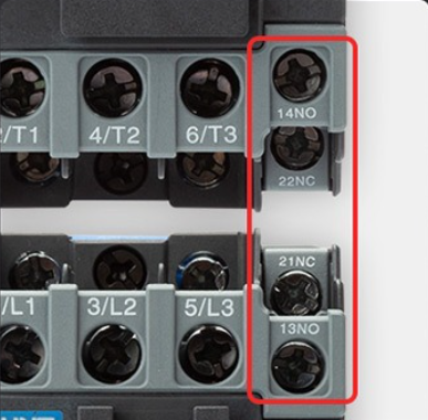
Note: The 06A-100A specification product comes with 1 normally open and 1 normally closed auxiliary contact.
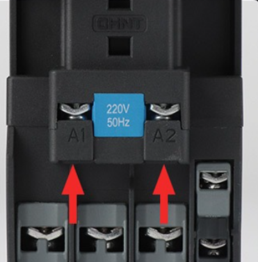
Model example: NXCF-12 220V indicates that the rated working current of the contactor is 12A when the main circuit voltage is 380V/400V under the AC-3 usage category. Each contactor body is equipped with 1 normally open and 1 normally closed auxiliary contact, and the coil control voltage is 220V AC with a frequency of 50Hz.
NXCF Series Selection Table for AC Contactors.
 Main Parameters and Technical Performance
Main circuit parameters and technical performance
| Contactor model | NXCF-06 | NXCF-09 | NXCF-12 | NXCF-16 | NXCF-18 | NXCF-22 | ||
| Shell level | 06~16 | 18~22 | ||||||
| Agreed free air heating current Ith(A) | 20 | 20 | 25 | 25 | 32 | 32 | ||
| Rated insulation voltage Ui(V) | ||||||||
| Rated impulse withstand voltage Ui mp(kV) | 8 | |||||||
| Rated connection capacity | current on:10×Ie(AC-3) or 12×Ie(AC-4) | |||||||
| Rated breaking capacity | Connect breaking current:8×Ie(AC-3) or 0×Ie(AC-4) | |||||||
| Rated working current Ie(A) | AC-1 | 20 | 20 | 25 | 25 | 32 | 32 | |
| 220V/230V | AC-3 | 6 | 9 | 12 | 16 | 18 | 22 | |
| AC-4 | 6 | 9 | 12 | 16 – | 18 | 22 | ||
| 380V/400V | AC-3 | 6 | 9 | 12 | 16 | 18 | 22 | |
| AC-4 | 6 | 9 | 12 | 12 | 18 | 18 | ||
| 660V/690V | AC-3 | 3.8 | 6.6 | 8.9 | 8.9 | 12 | 14 | |
| AC-4 | 3.8 | 6.6 | 8.9 | 8.9 | 12 | 12 | ||
| Rated control power | AC-3(kW) | 220V/230V | 1.5 | 2.2 | 3 | 3 | 4 | 5.5 |
| 380V/400V | 2.2 | 4 | 5.5 | 7.5 | 7.5 | 11 | ||
| 660V/690V | 3 | 5.5 | 7.5 | 7.5 | 10 | 11 | ||
| Electrical lifespan (10000 cycles) | AC-3 | 120 | ||||||
| AC-4 | The specific information is in the electrical life curve chart | |||||||
| Mechanical lifespan (1000 cycles) | 12 000 | |||||||
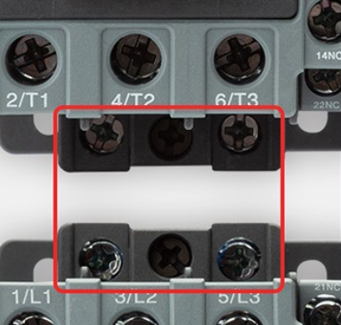
| Main contact structure type | 3 normally open | |||||||
| SCPD Used fuses | gG20 | gG20 | gG25 | gG25 | gG32 | gG32 | ||
| Matching thermal overload relay | Type | NXRF-25 | ||||||
| Number of built-in auxiliary contacts | 3P | 1 open 1 close | ||||||
| 4P | – | |||||||
| control circuit | Contactor model | NXCF-06 | NXCF-09 | NXCF-12 | NXCF-16 | NXCF-18 | NXCF-22 | ||
| Main circuit wiring | Cable connection (mm²) | Prefabricated flexible wire | 1 | 1~4 | 1.5~6 | ||||
| 2 | 1~2.5 | 1.5~4 | |||||||
| Hard wire | 1 | 1~4 | 1.5~6 | ||||||
| 2 | 1~4 | 1.5~6 | |||||||
| Tightening screw size | M3.5 | M3.5 | |||||||
| Tightening torque (N·m) | 1.2 | 1.2 | |||||||
| Control circuit connection | Cable connection (mm²) | Prefabricated flexible wire | 1 | 1~1.5 | |||||
| 2 | 1~1.5 | ||||||||
| Hard wire | 1 | 1~1.5 | |||||||
| 2 | 1~1.5 | ||||||||
| Tightening screw size | M3.5 | ||||||||
| Tightening torque (N·m) | 1.2 | ||||||||
| Contactor model | NXCF-06 | NXCF-09 | NXCF-12 | NXCF-16 | NXCF-18 | NXCF-22 | |
| Coil control power supply | Inter flow 50Hz | 24、36、42、48、110、120、127、220、230、240、277、380、400、415、440、460、480、525、600、660 | |||||
| continuous current | – | ||||||
| range of motion | Pull-in | (70%~120%)Us | |||||
| Released | (20%~65%)Us | ||||||
| Average power consumption of coil (VA) | Open | 50~70 | |||||
| Hold | ≤ 9.0 | ≤ 9.5 | |||||
| Heat loss rate(W) | alternating | 1~3 | |||||
| constant current | – | ||||||
| Main contact action time(ms) | close | 12~40 | |||||
| Break | 4~25 | ||||||
| Type | Amax | Bmax | Cmax | Dmax | Emax | Fmax | Gmax | a1 | b1 | C1 | a2 | b2 | C2 | e | f |
| NXCF-06~16 | 45.5 | 75 | 88 | 70 | 126.5 | 146.5 | 90 | 35±0.31 | 48±0.31 | Φ4.5 | – | – | – | 10.6 | 7.8 |
| NXCF-18~22 | 45.5 | 75 | 88 | 70 | 126.5 | 146.5 | 90 | 35±0.31 | 48±0.31 | Φ4.5 | – | – | – | 11.4 | 9.2 |
| NXCF-25~38 | 56.5 | 87 | 93 | 81 | 131.5 | 151.5 | 95 | 40±0.31 | 48±0.31 | Φ4.5 | – | – | – | 14.2 | 10.6 |
| NXCF-40~65 | 77 | 129 | 118 | 102 | 156.5 | 176.5 | 121 | 40±0.28 | 105±0.57 | Φ6.5 | 64 | 105 | Φ6 | 20 | 9.5 |
| NXCF-75~100 | 87 | 132 | 127 | 112 | 165.5 | 185.5 | 129 | 40±0.28 | 105±0.57 | Φ6.5 | 74 | 112 | Φ6.2 | 24 | 13 |

1:Instructions for use in abnormal environments
Explanation of using correction factors in high-altitude areas
- The GB/T 14048.1 standard specifies the relationship between altitude and impulse withstand voltage. When the altitude is ≤ 2000m, it has no significant impact on product performance.
- When the altitude is greater than 2000m, the air cooling effect and the decrease in rated impulse withstand voltage must be considered, so the manufacturer needs to negotiate with the user for design or use.
- The following table provides the correction factors for the rated impulse withstand voltage and rated working current at an altitude greater than 2000m and with the rated working voltage unchanged.
| above sea level(m) | 2000 | 3000 | 4000 | 5000 |
| Rated impulse withstand voltage correction factor | 1 | 0.88 | 0.78 | 0.7 |
| Rated working current correction factor | 1 | 0.92 | 0.9 | 0.85 |
Instructions for use in abnormal temperature environments
- The GB/T 14048.1 standard specifies the normal working environment temperature of the product, and its use within the normal working environment temperature range has no significant impact on product performance.
- When the working environment temperature is higher than+40 ℃, it is necessary to consider that the allowable limit temperature rise of the product must be reduced. The rated working current must be lowered, and the number of contactors installed in standard components must be reduced. Otherwise, it may damage, shorten the product life, and reduce work reliability, and also affect the product’s operating range; When the working environment temperature is below -5 ° C, it should be considered that the grease used for insulation and lubrication will freeze at low ambient temperatures, leading to product malfunction. Therefore, manufacturers and users need to negotiate for design or use.
- The following table shows the correction factors for the rated working current when the working environment temperature exceeds+55 ℃ and the rated working voltage remains unchanged.
| Temperature(℃) | 55 | 60 | 65 | 70 |
| correction factor | 1 | 0.93 | 0.875 | 0.75 |
- +At 55 ℃~+70 ℃, the suction voltage range of the AC contactor is (90%~110%) Us, and the test results for (70%~120%) Us and (75%~120%) Us are at room temperature and 40 ℃ cold state. Instructions for Capacity Reduction during Use in Corrosive Environments
- The impact on metal components
Chlorine Cl2, nitrogen dioxide NO2, hydrogen sulfide H2S, sulfur dioxide SO2
Copper: The thickness of copper sulfide coating in chlorine gas environment will be twice that of normal environment, and it will be basically the same in the presence of nitrogen dioxide.
Silver: When silver contacts or silver coated contacts are used in SO2 and H2S environments, the surface of the contacts will darken, forming a silver sulfide coating that increases the contact temperature and can cause contact damage. In a humid environment, when Cl2 and H2S are present simultaneously, the thickness of the coating will increase by 7 times. If H2S and NO2 are present simultaneously, the thickness of the silver sulfide coating will increase by 20 times.
- to be considered in selection
In industries such as oil refining, steel, paper making, artificial fibers (nylon), or industries that generally use sulfur, equipment used may experience pressurization, also known as “oxidation” in the industrial sector. take
Installing equipment in the computer room does not guarantee that it will not be oxidized. In order to ensure that the air pressure in the computer room is slightly higher than atmospheric pressure, the air inlet is generally shorter, which does reduce external pollution to a certain extent. However, after 5 to 6 years of operation, the equipment inevitably corrodes and oxidizes. For this purpose, in working environments with corrosive gases, the equipment needs to be reduced in capacity, with a reduction factor of the rated value multiplied by
At 0.6 (maximum 0.8), this method can reduce the rate of accelerated oxidation due to temperature increase.
Instructions for parallel use of poles and poles
- After parallel connection of poles, considering the distribution of long-term unstable currents, the rated current of parallel poles needs to be adjusted, as shown in the table below:
| Parallel series | 2 | 3 | 4 |
| correction factor | 1.6 | 2.25 | 2.8 |
Note: If the product is applied in a dusty environment,Please select and install a dust cover AXC-1、AXC-2、AXC-3、AXC-4。